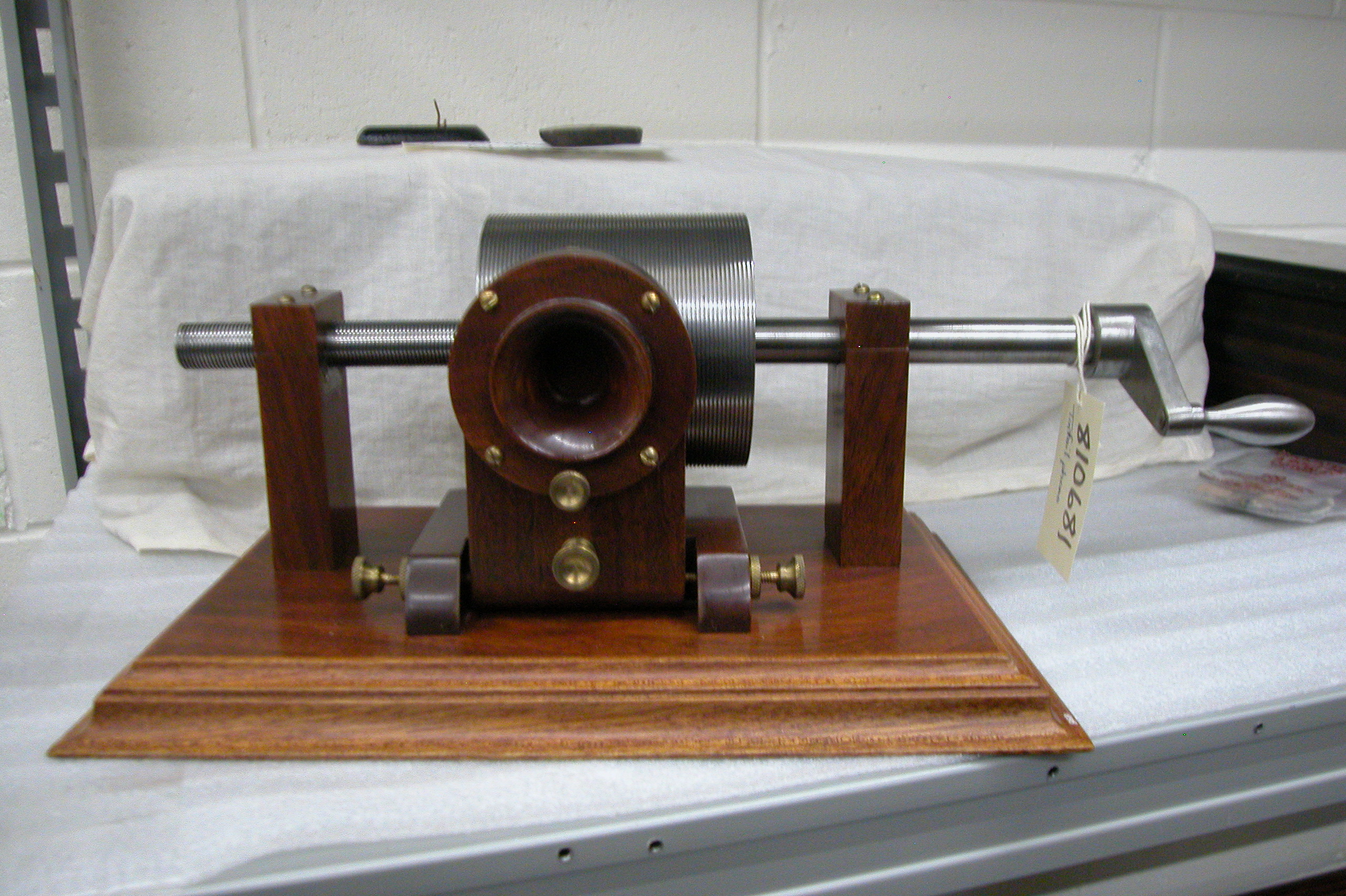
It took more
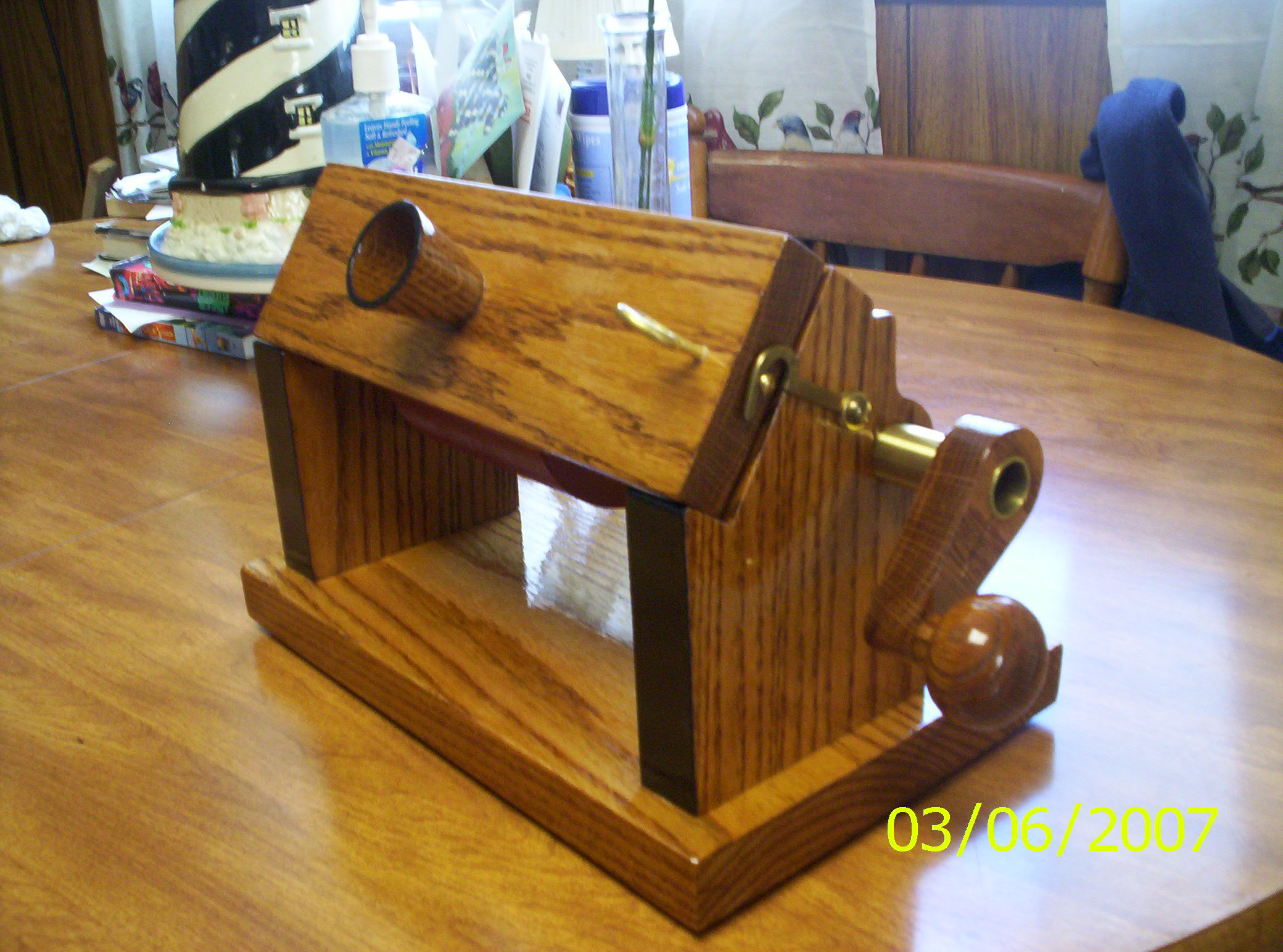
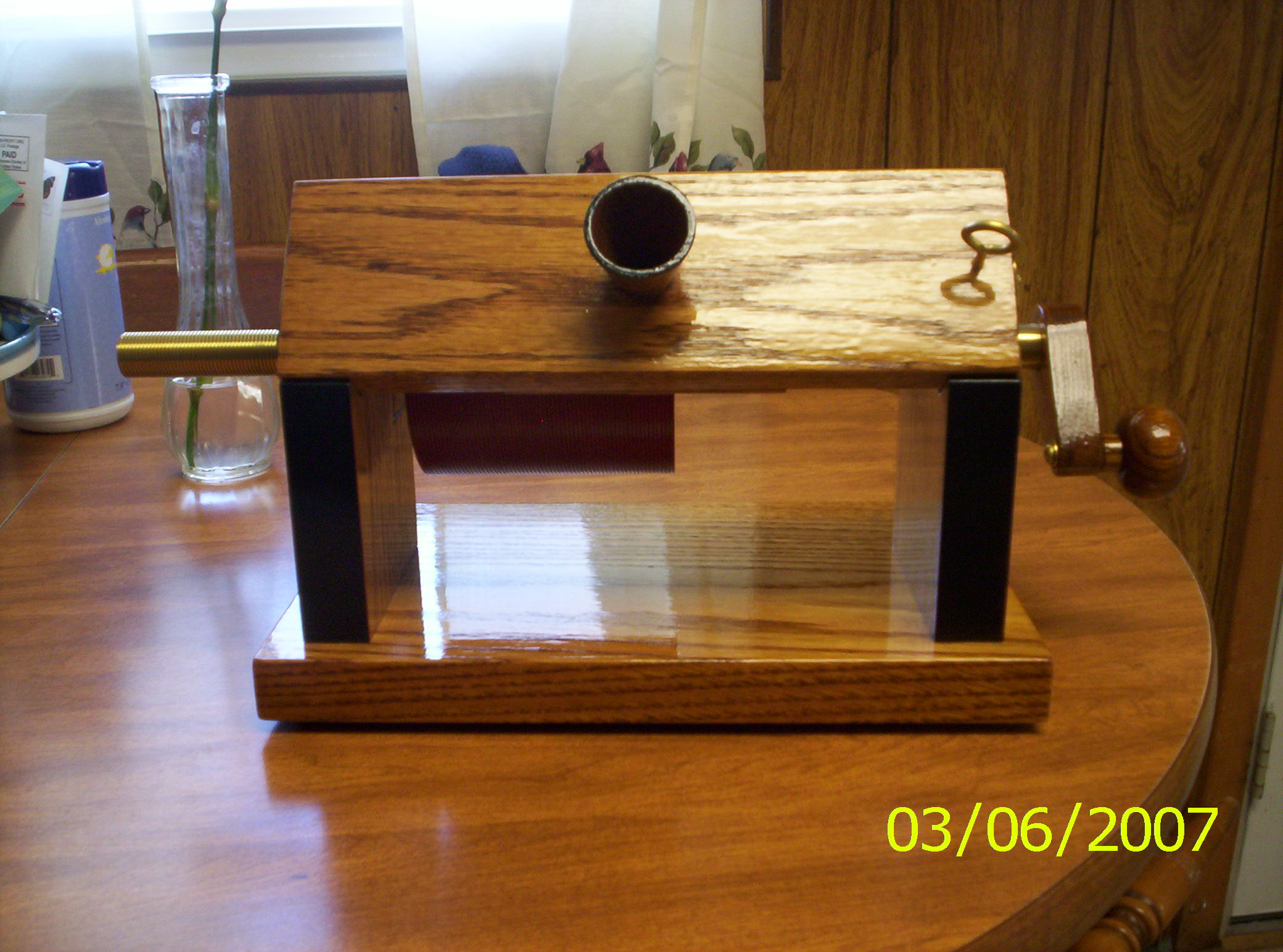
than 40+ hours for this one [i.e., the phonograph
pictured above]. I even experimented with
different diaphragms, and found five and one-half
thousandths thick aluminium printing plate material works
the best. Instead of sandwiching the diaphragm between
(over) the diaphragm support and cover plate, I inserted
the diaphragm into the cavity, and gasketed it both sides
with the cover plate keeping it under more tension than if
it was just held in place between the two.
I couldn't find a porcelain mouthpiece anywhere, so I
had the mouthpiece made from wood. I found a old hardware
store that had the hook, new ones just didn't have the fit
or character. The screw eye was hand made, another part
unavailable anywhere.
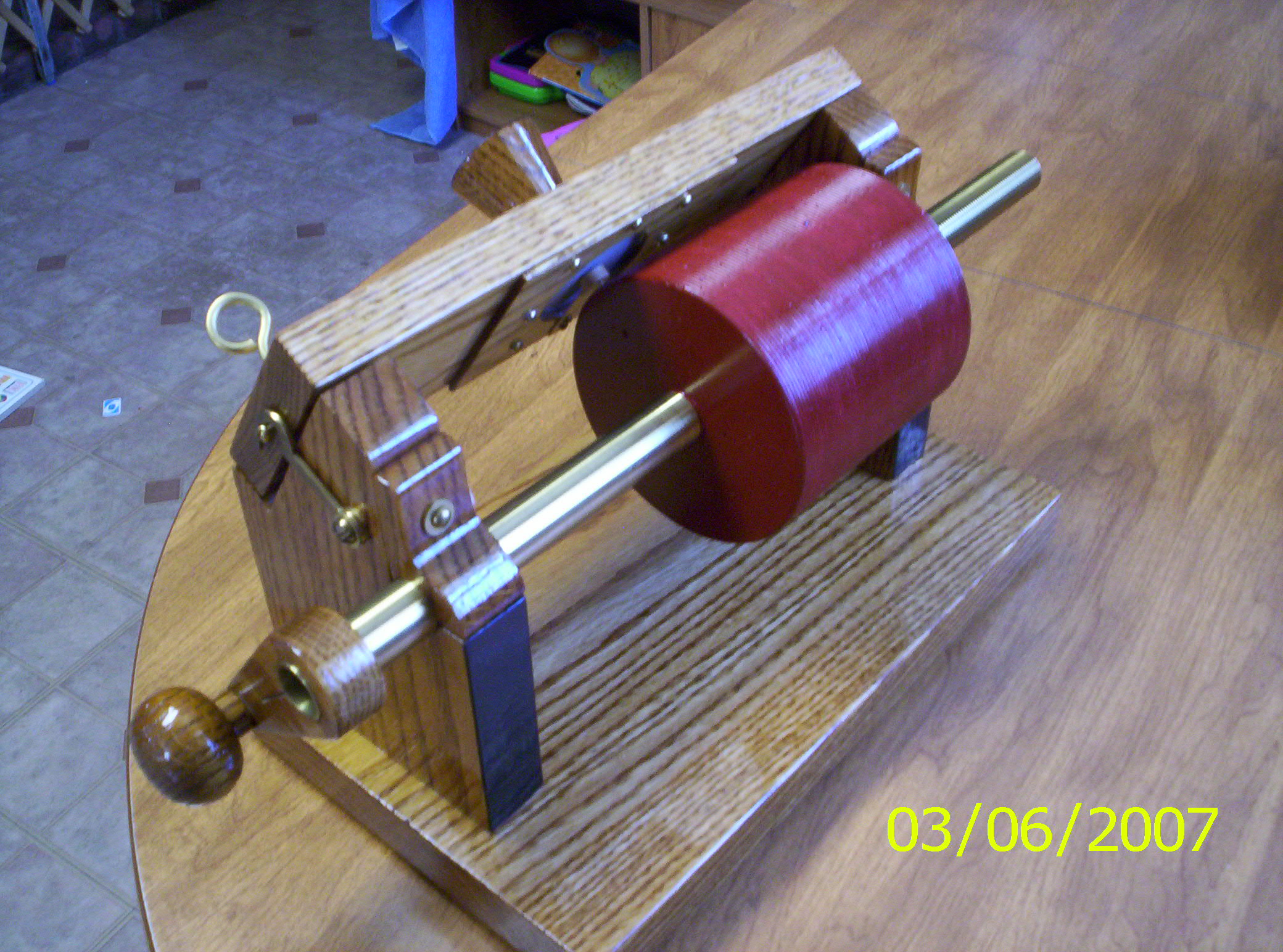
Making the plaster-of-Paris cylinder was an event in
itself!! I made the mix way too thick the first time, and
it had voids. So, out came my late Dad's brick hammer and
I had to smash it off, what a time. I then made a new
mould, and made the plaster very "soupy" and it worked
great. No voids. Then there is another trick to fine tune
the cylinder to the frame that has to be done before
painting. There is so much to it beyond what the plans
show that comes from experience making them. I'd
gladly help anyone through it if they need the help.
Anytime!
* *
* * *
There is a
certain way to finish off the cylinder so it is correct
and true. First, the grooves need to be cut so the
groove is truncated, and not a sharp point, so the foil
sits flat. If the groove is too pointed, the foil
won't work as well because it doesn't have the support
underneath. You need to go over the face with a very small
very fine piece of sandpaper glued to a smooth strip of
wood. It goes between the diaphragm and cylinder,
and you crank it through several or more times. I
can explain more fully later, but it's one of many "little
things" I have incorporated into making these.
*
* * *
*
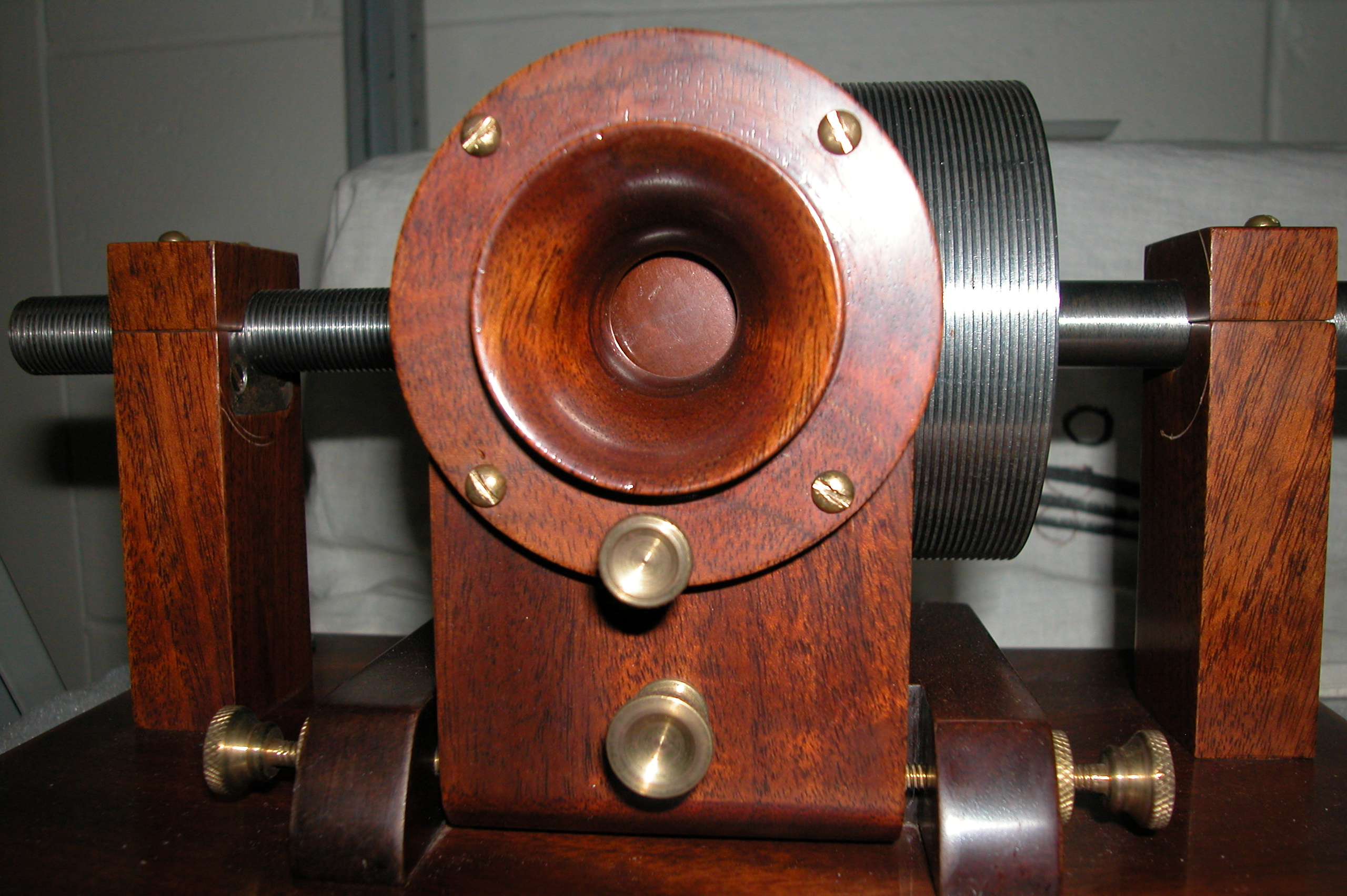
For the plaster mandrel model: Quarter-sawed oak looks good for this machine, and is an
appropriate thing to use. If you can get a 1 13/16"
thick piece, six feet long,and12" wide, and plane down
what's needed, and save some of the 1 13/16" material for
the crank knob, the machine will have been made from one
piece of wood, and better looking!
1-Blow up the side profile [with crank] on photocopier
so the cylinder diameter is 4 1/2" to use as a template.
2-Cut a 1" thick board 15" long and 4 13/16" wide, then
cut that board exactly in half, yielding two 7 1/2"
pieces. Make sure all ends are perfectly square!!
These are for the two upright standards. Cutting it
this way assures the two standards have the same grain
pattern than if cut from separate stock. Also, the
front and back edges don't have to be scrollsawed, just
the curves and area where the diaphragm support goes.
When tracing them out, be sure to keep the two pieces
oriented so the grain is the same. After tracing,
put a pin point hole through the center shaft area of the
print, and mark the wood there for a drilling reference.
After that, cut out the crank handle from the template and
use that for marking out a crank.
3-Before scrollsawing, drill the pilot holes in the
bottom of each standard. Secure them so the drill
goes in straight and can't "walk".
4-Drill the 3/4" shaft hole where marked. Since
you made the two pieces identically in height, you can
make a "L" bracket as a guide and support from wood
clamped to the drill press. Drill one to a time, and
place a scrap piece of wood underneath so the drill bit
won't chip going through. When you do the second
one, make sure the area is clear of wood dust so the piece
aligns as the first one did, exactly in the "L" guide.
5-Before scrollsawing, use double sided scotch tape and
attach the pieces together, so you'll be cutting them one
time as identical. Make sure the pieces are attached
perfectly identical. This way there will be a lot less
sanding to make them the same. Cut out the two slots
for the shaft as the final step. Make sure the side
[horizontal] cut is exactly in the center of the shaft
area so the shaft is easy to install.
*
* * *
*
For a lathe
turned cylinder: Use .065" thick walled 3/4" O.D.
brass tubing, available from McMaster-Carr of N.J.
Make it an even 16" long, and the threaded section 5 1/4"
long. It will work a lot smoother if the shaft is
threaded as a square cut groove.
1-Make the paper mould 5" in diameter, and 4 1/2" wide.
2-Align paper mould so exactly 5" of the threaded end is out of the mould
area.
3-Make the plaster "soupy" and not stiff so it will pour without voids.
4-When hardened up, remove mould and bake for two hours very gentle heat
at 120 to 140 degrees. Do not coat it with paraffin!
5-True up the threaded side of the plaster cylinder until 5 3/16"of
threaded shaft is exposed, then true up the opposite side
until the width is exactly 4".
6-Turn down the diameter to 4 1/2".Patch any air bubbles with plaster,
sand VERY lightly with the circumference, and let dry.
7-Cut a "V" groove into the surface, until it just forms a fully pointed
edge groove. Chamfer the two sides if desired.
8-Place the assembly in the frame, and tighten the hold down caps
securely.
9-Fashion a 1/8" thick x 6" long x 1/4" wide board that has one of the
1/4" faces sanded smooth and square [no ripples or warps]
for gluing a medium fine strip of sandpaper to.
10-With the diaphragm holder off the machine, and the standards square,
secure, and tight on the baseplate, place the sandpaper
block [sandpaper against the plaster] between the cylinder
and diaphragm support.
11- Crank several or more times from left to right so every time a VERY
LIGHT amount of plaster dust is removed. Each time
you will be truing the cylinder to the frame, a very
important process. Keep the diaphragm support tight
to the block, and crank slowly. Hold it so the block
can be grasped near the bottom of the support. When
the sharp "V" groove is sanded into a truncated groove the
process is complete. You want the groove into the
surface only. The grooves will no longer have sharp
points. The foil will rest flat on the surface this
way.
12-The cylinder can be painted with oil based paint. Two coats on
the sides, and only one good coat on the face or the
grooves will be filled in. If the paint is thinned
somewhat it will be easier to use.
*
* * *
*
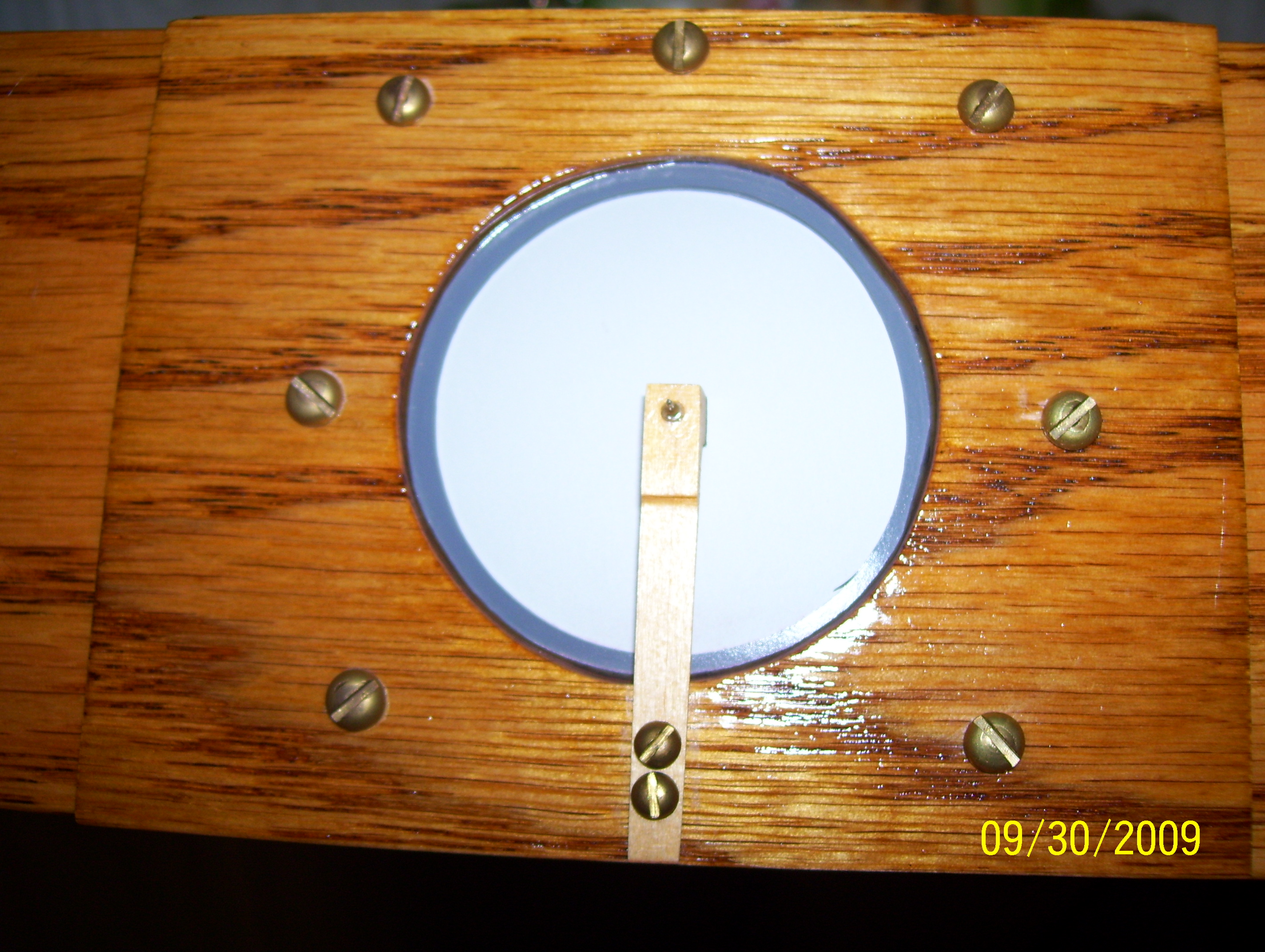
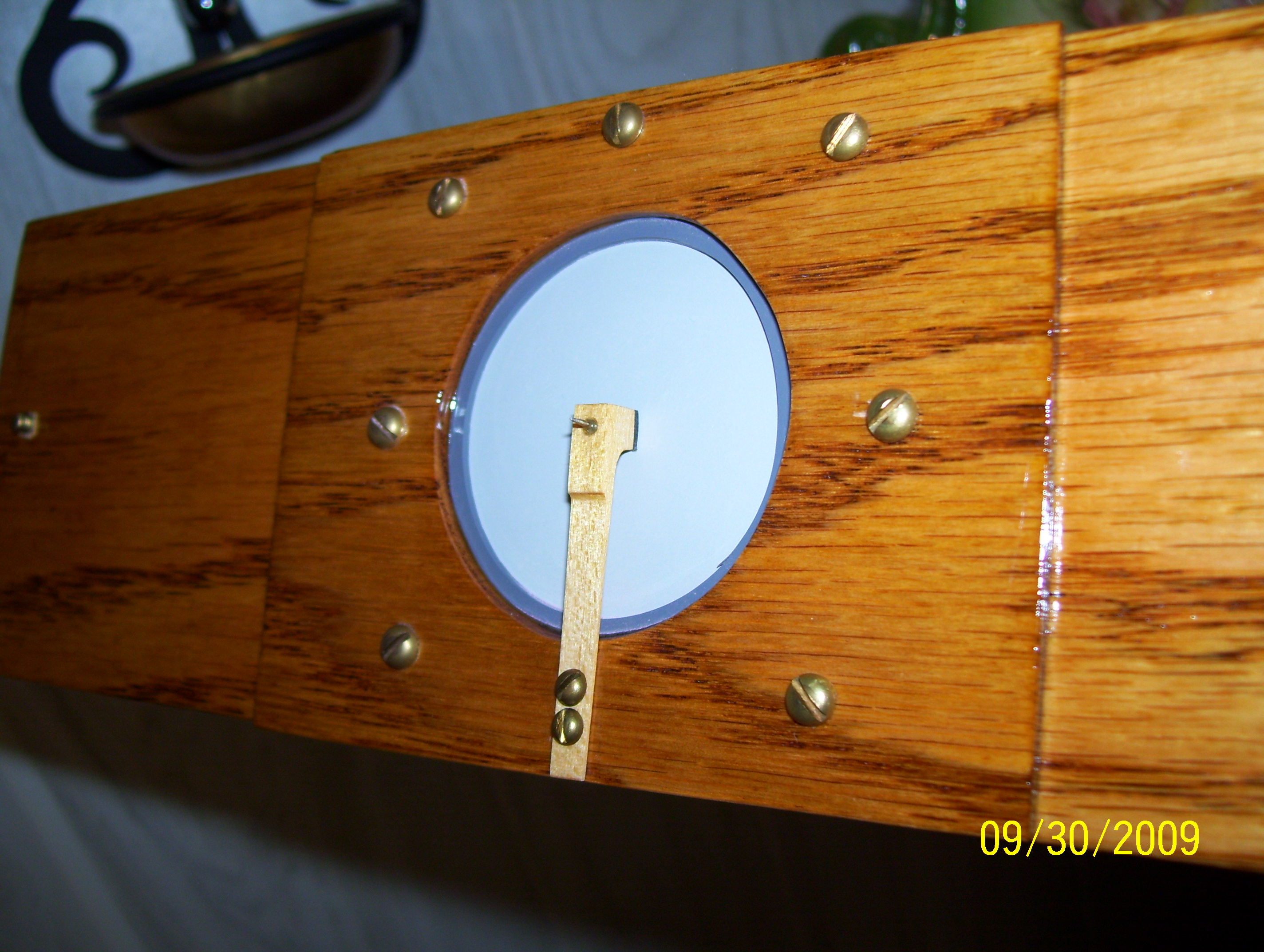
For the
diaphragm assembly:
Make sure the recess in the diaphragm support is bored
out true on a drill press, and not at an angle as a hand
drill will do, so the diaphragm will be at the same
parallel plane to the cylinder. Drilling it about
1/8" should do fine. The deeper it's drilled will
take more gasket thickness.
Put the diaphragm into the recess rather than over it,
gasketed both sides, so when screwed down it will compress
tight. It can be made tighter this way than if the
diaphragm is larger and placed over the recess.
I use PVC shower liner for gaskets as the outside
gaskets, with thin paper as the ones that mate to the
actual diaphragm. Make the thickness and amount of
gaskets so when the diaphragm holding plate is resting on
the support [flat and upright on a table] the diaphragm
and gaskets are slightly sticking up before screwed down.
Five and one half thousandths thick aluminium printing
plate material is the best I've used for the diaphragm.
When making the stylus bar, drill the needle hole
slightly larger than the needle you will be using, and use
Elmer's glue, and not crazy glue, so it can be easily
removed later if needed. Make sure the bar is
vertical and straight to the diaphragm, as the print
shows, when installed. Glue the gasket material
directly to the diaphragm side of the bar, and use a very
light coat of spray varnish, including the gasketed area
so it will be smooth. Too much or too thick of a
coat will reduce the spring action of the wood. When
they say "A delicate wood spring" they really mean it.
If it's 3/16" wide across is good. Try to limit the
width to that. Too wide and the sensitivity is lost,
and it takes a lot more volume to record. Make the
"mallet" about 3/32" tall. Use white pine, the kind
that your fingernail will easily indent, and not yellow
pine which isn't as flexible.
*
* * *
*
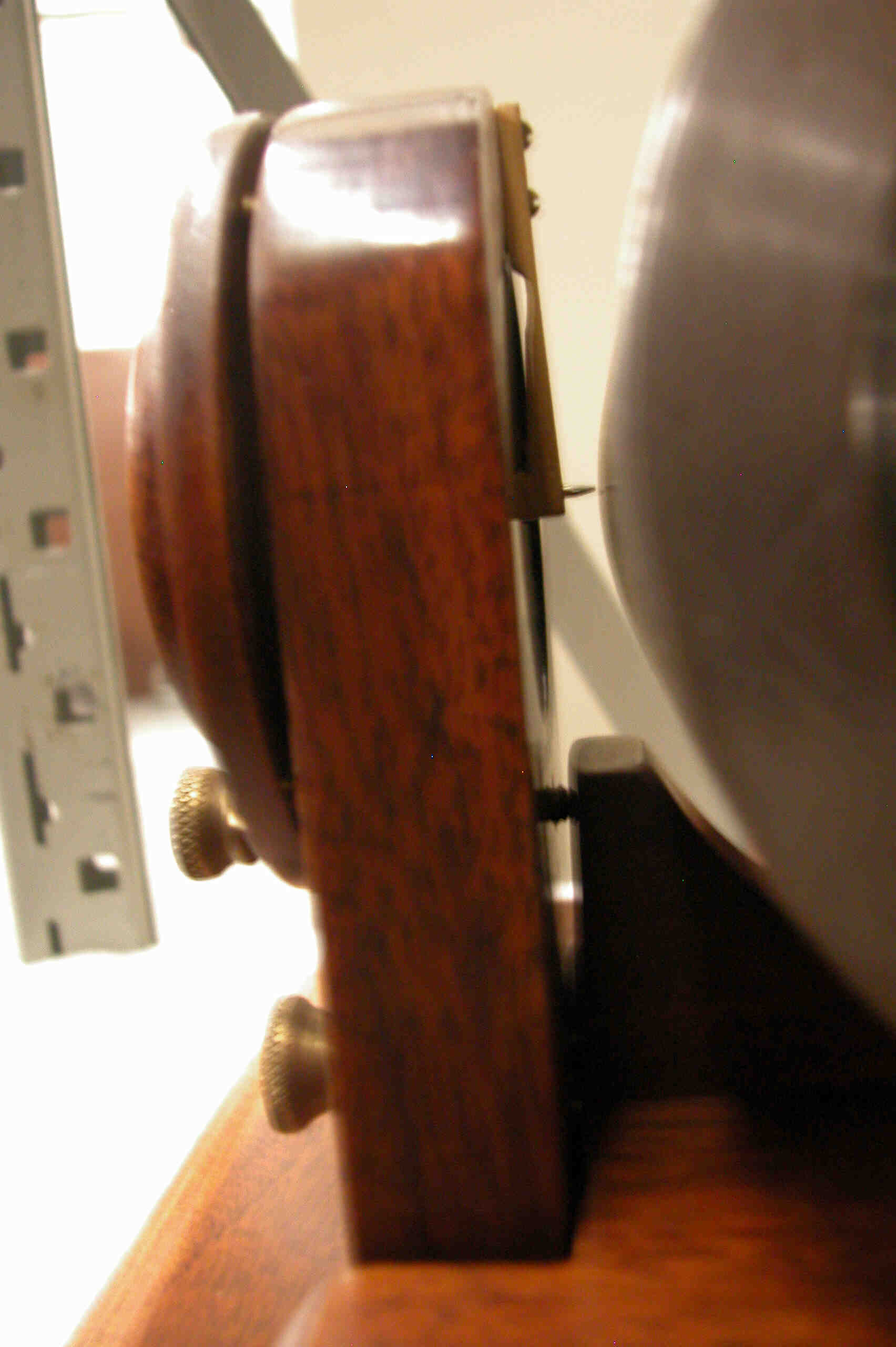
Before the diaphragm support hinge is installed on the
left side standard, make sure to find a good quality hinge
that has a good fit, and doesn't have a lot of play. Try
to find an old American made one, if possible!
Place a thin shim stock [thick paper, or something similar] under both
sides of the diaphragm support when it rests on the
standards, and the same material behind both sides of the
diaphragm support. Then mark out the hinge area for
the screws. This way, there is a little clearance on
all sides where the three pieces meet and it won't have a
bind and the diaphragm support won't rub on the right side
standard when closed.
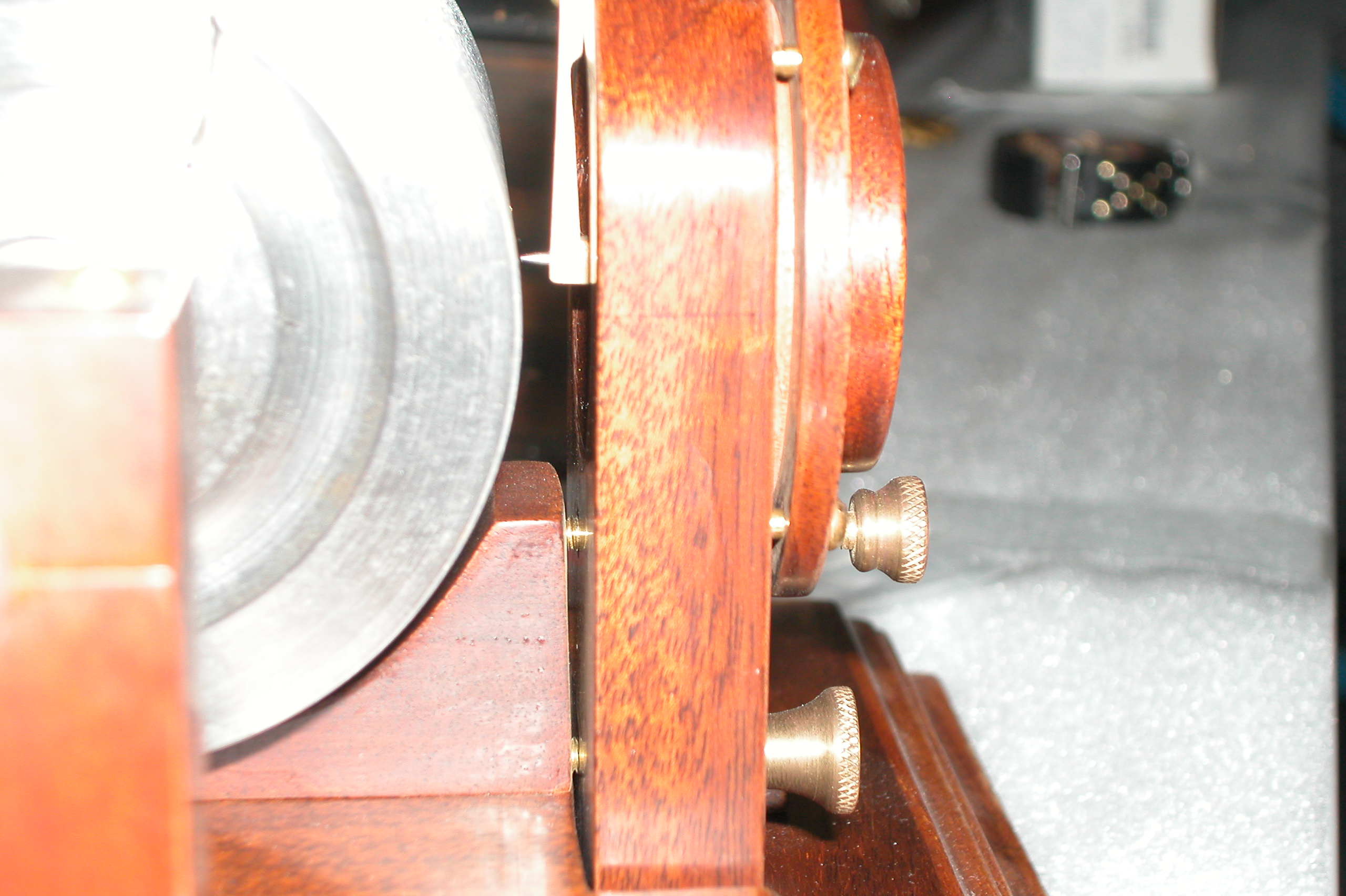
I have found that using brass flat headed screws makes a genuine
authentic machine. The brass screws match the shaft,
and if flat headed screws are used, shows the hardware of
1878. Phillips screws weren't invented then, and
don't reflect the period when it was made.
*
* * *
*
I think it
really is neat that these still can be made. The
kids at school really marvel at it. And when I first bring
it in, the teachers give me a skeptical look like it can't
work. When it does, it reminds me of the looks of
the "S-A" staff when they first heard it.
Another very important part of this to me is the
builder is making something authentic from actual 1878
plans. There's really not many things that can be said like
that nowadays! |