Phonozoic Text Archive, Document 118
How to Build a Working Phonograph
With Drawings Made to a Scale of Half Size (1878)
Scientific American Supplement No. 133, July 20, 1878, p. 2112.
Click on images to open in a new window and enlarge
Now that Edison has invented the Phonograph, it is easy enough to make one, and every one wonders that it had not been done before. The Phonograph, truly wonderful as it is, is exceedingly simple and may be made at a slight expense.
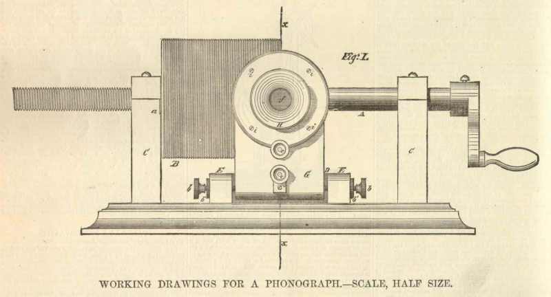
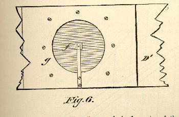
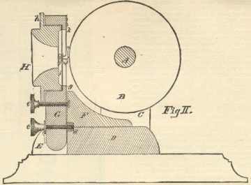
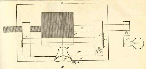
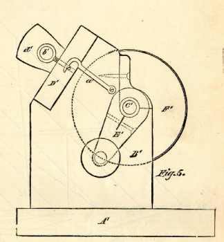
The accompanying engravings represent two forms of a small phonograph which will work admirably, and do all that any of the hand machines will do. In the illustrations, which are half size, Fig. 1 is a front elevation. Fig. 2 is a vertical section on line x x in Fig. 1. Fig. 3 is a plan view of a cheap form of the phonograph. Fig. 4 is a transverse section on line y y in Fig. 3. Fig. 5 is an end elevation, Fig. 6 a face view of the diaphragm, and Fig. 7 shows details of the screw bearing.
The shaft, A, in Figs. 1 and 2, is � inch in diameter, 15 � inches long, and has upon one end a 2 inch crank, and is threaded for five inches from the other end. The iron cylinder, B, which is 4 inches long and 4 inches in diameter, is bored axially, and secured to the shaft 5 inches from the threaded end, and has a screw cut upon it of the same pitch as that upon the shaft. The pitch of the thread should be 16 to the inch, and the form of the thread should be square.
The shaft, A, is journaled in wooden standards, C, which are 1x1 � in. in transverse section. The distance from the base piece to the center of the shaft is 3 � inches. The base piece is 7x11 � inches face and 1 inch thick.
The standards may each be secured to the base by two common wood-screws. The distance between the standards is twice the length of the cylinder, or 8 inches. A steel plate, a, is fitted to the groove of the screw threads in the shaft, and is secured to the side of the standard, which is slightly beveled to conform to the pitch of the screw.
Under the cylinder and centrally between the standards a block, D, which is 3 � x 3 � inches and 1 inch thick, is firmly secured to the base piece. To opposite edges of this block are secured the cross pieces, E, and to the middle of the block a stop, F, is secured which is of the form shown in the engraving, and 1 inch thick.
Pointed screws, b, which are provided with lock nuts, b�, pass through the front ends of the cross pieces, E, into metallic plugs inserted in the edges of the diaphragm support, G, and form its pivots. This support is held in position by the screw, c, which passes through it to the nut, d, which is externally threaded and screwed into the block, D, and stop, F.
The position of the support, G, is regulated by the screw, e, which passes through it and rests against a metallic button, which is inserted in the stop piece, F.
The diaphragm support, G, is � inch thick and 3 inches wide, and is bored out to receive the diaphragm, f, and mouthpiece, H. The opening in the support, G, is of two diameters; the larger part, which receives the mouthpiece and diaphragm, is 2 3/8 inches in diameter, and the smaller part exactly 2 inches, leaving a flange, g, which is 3-16 in. wide and 1/8 in. thick, and leaving 2 inches of the diaphragm exposed.
The mouthpiece, H, has an annular bearing surface which corresponds in width to the flange, g. The smaller part of the opening through the mouthpiece is � in. in diameter.
The mouthpiece has a flange, h, for receiving screws, i, by which it is secured to the diaphragm support.
The diaphragm, f, is clamped between two rings of blotting paper, and is damped by two or three pieces, j, of elastic tubing placed between it and the inner surface of the mouthpiece, H.
A delicate wood spring, k, having the head or mallet, c, is secured by screws to the diaphragm support, G, and the head, l, rests upon a thin piece, m, of elastic rubber, which is placed upon the center of the diaphragm.
The best material for the diaphragm is thin ferrotype plates, procurable at the photographer�s. The head, l, is drilled to receive a needle, n, which projects about 1/16 in. and is quite sharp. The point, however, should be slightly rounded and shaped somewhat like the point of a leather awl, with the edge arranged parallel with the axis of the cylinder. The width of the point must be very slight indeed, and the needle must always be kept in good condition. If the needle is too sharp it will cut and scrape the tinfoil; if too dull, the articulation will be muffled. The needle may at any time be sharpened without removing it from the instrument by using a small oilstone slip. Before placing tinfoil on the cylinder the needle must be adjusted by the screws, b, so that it will strike exactly in the center of the space between the screw threads.
The tinfoil used with the instrument should be rather stout�about 15 square feet to the pound�and it should be cut into pieces 4x13 inches.
The foil is smoothed out on a glass plate and wrapped smoothly around the cylinder, and one end, after being gummed or coated with a little shellac varnish, is lapped over the other end and the joint is carefully smoothed.
It is obvious that the direction in which the foil is lapped depends upon the direction in which the cylinder is turned. While the cylinder may be turned either way, it is found preferable to turn it in a right-handed direction, and the foil accordingly should be lapped from right to left.
Having placed the tinfoil, the diaphragm is adjusted by means of the screws c e, so that the needle point will make a slight groove in the tinfoil, as the cylinder is turned. After this adjustment the screw e need never be changed.
Now, by speaking rather loudly in the mouthpiece, and at the same time turning the cylinder, the speech will be recorded upon the tinfoil. After loosening the screw c, the cylinder may be turned back to the point of starting. The needle may again be brought into contact with the foil by turning up the screw c, when, by turning the cylinder forward, the speech or other sounds will be reproduced.
It is found advantageous to speak to the instrument through a short tapering tube, the smaller end of which is � inch in diameter and the larger end 1 � inch in diameter. The tube should be about 4 inches long.
When the instrument is made to speak a conical paper resonator, 16 or 18 inches long and 5 or 6 inches diameter at the larger end and � in. diameter at the smaller end, should be inserted in the mouthpiece, as it greatly re-enforces the sounds.
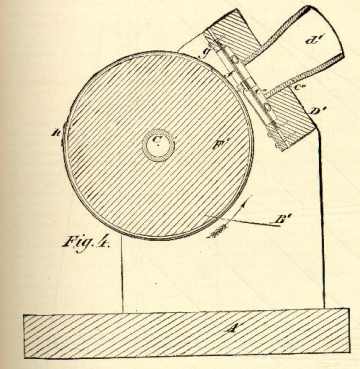
Figs 3 to 7, inclusive, represent a phonograph for which the materials may be purchased for $1.50. In this instrument the base piece, A�, is 7 x 11 � inches and 1 inch thick. The standards, B, are of the form shown in the engraving, and 1 inch thick. They support the shaft, C�, 3 � inches from the base, and are cut off diagonally to receive the diaphragm support, D�, which is hinged at one end and fastened by a hook a�, at the other end.
A screw eye, b�, having its point filed off, is screwed through the free end of the diaphragm support and rests against the standard, B�, and serves as an adjusting screw for regulating the needle. There is a � inch hole, c�, exactly in the middle of the part, D�, for securing the mouthpiece, d�, and in the under side of the part, D�, concentric with the hole, c�, there is a shallow circular recess, c��, which is 2 inches in diameter.
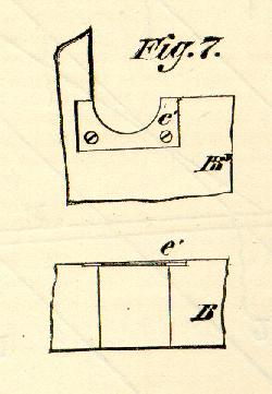
The shaft, C�, is made of a piece of mandrel drawn brass tubing, 15 � inches long and � inch external diameter. It needs no turning, and it may be threaded by any steam or gas filter. The length of the threaded portion should be the same as in the phonograph described above, but the lead may be somewhat coarser, say 14 or even 12 to the inch. The nut is made with a steel plate, e�, screwed to the standard as in the other case.
The crank, E�, is of wood, and is split from the shaft toward the handle and clamped tightly on the shaft by the screw shown in dotted lines.
The cylinder, F�, in this machine is made of plaster of Paris, and is turned off in the frame.
The method of making the cylinder is as follows: Drill two holes through the shaft at right angles to each other and insert two short pins, which will hold the cylinder in place after it is cast.
Strike two concentric circles on a piece of pasteboard, one � inch and the other 4 � inches diameter. Put 7 inches of the smooth end of the shaft through the � inch hole, and support the pasteboard and shaft, so that the shaft is vertical and at right angles to the pasteboard. Take a piece of stout, smooth paper, 4 inches wide and 18 or 20 inches long, and form it into a cylinder 4 � inches diameter, and fasten the overlapping ends by means of pins or a string, and set it upon the 4 � inch circle on the pasteboard. Secure it in place with a little plaster of Paris.
In a suitable vessel place 1 quart of water. Sprinkle into it 4 lbs. Of very fine plaster of Paris, allow it to settle, pour off the surplus water, stir the batter rapidly, but be careful that it does not become filled with air bubbles; pour the plaster into the paper cylinder and allow it to set; when it becomes hard and before it dries, remove the paper mould, and place the shaft, C�, in the boxes in the standard and secure the box caps by a screw as shown in the end elevation (Fig. 5). Fit a plug to the mouthpiece hole, c�, and drive through it a turning chisel. Block up the free end of the part, D�, and turn the shaft.
The cylinder revolves under the chisel, and is at the same time moved lengthwise by the screw. The machine is thus temporarily converted into a lathe. By gradually lowering the chisel, as the cylinder is made to traverse back and forth, the cylinder will be reduced in diameter and made true.
When it is 4 � inches in diameter, it is removed from the frame and dried in a warm (not hot) oven. When dry, and while it is warm, it is coated with paraffine, which is allowed to soak in.
When it becomes cool it is placed in the frame, and a V-shaped thread-cutting tool is substituted for the turning chisel, and the thread is cut in the surface of the cylinder by causing the cylinder to revolve under the cutting tool as in the case of turning.
The thread-cutting tool must take very light chips, otherwise the cylinder will be rough.
The V-shaped groove need not be deep, and the top of the thread should be wider than the groove. The diaphragm, f, is clamped between paper rings, over the recess, c��, by means of a thin board, g, having a circular aperture which corresponds in diameter with the recess, c��.
The diaphragm is damped with short pieces of rubber tubing, and the needle is mounted in the same manner as in the machine shown in Figs. 1 and 2.
The mouthpiece is of porcelain, such as is used for speaking tubes.
The tinfoil is wrapped around the cylinder and lapped as shown at h.
The arrow indicates the direction in which the cylinder must be turned.